Micromachining
During the 2015-2016 school year, I worked with Dr. Shiv Kapooor on a way to create low-cost lense molds for smartphone cameras. The end result of the project was a toolholder providing manual horizontal adjustment for a TiAlN (Titanium Aluminum Nitride) coated carbide turning bit.
The project was in collaboration with FoxConn Interconnect Technologies, the primary manufacturer of the iPhone.
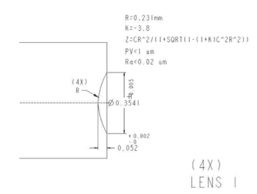
An axisymmetric specification of the 4x zoom lens is shown below. Most iPhone’s are \(~7 mm\) in thickness with most of that space devoted to non-camera components. A 4x zoom lens in the limited space available is possible, but only in the micrometer (\(10^{-6} m\)) space. The lens specified below is \(354.1 \mu m\) in diameter and \(52 \mu m\) in depth. As a point of comparison, the average human hair is \(80 - 100 \mu m\) in width.
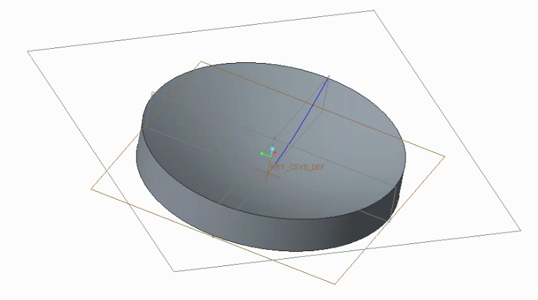
My objective was to design the tooling to make the lens mold itself; each lens mold could be used to create many lenses by pouring in molten glass into the mold. A CAD rendering of the lens mold is shown below.
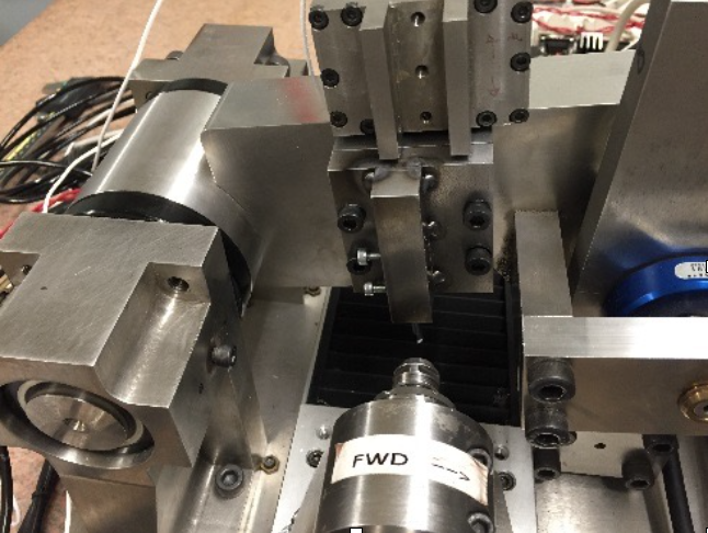
The turning tool schematic is shown below. In order to achieve the required geometry, it was absolutely essential to center the turning bit at the center of the workpiece. Options for CNC adjustment included angular motion about the z-axis (the axis that comes off the page in the schematic) and translation along the z-axis. For the small size of the part, the angular motion is largely equivalent to translation along the x-axis. The turning tool was originally designed to ensure maximum stiffness for turning operations, thus helping towards the goal of \(20 nm\) smoothness. One missing axis of freedom is translation in the y-direction. Permanent offsets in the x,y plane result in an inability to cut through the actual center of the part in a satisfactory manner. This was the principal problem our part was designed to solve.
The problematic cross-sectional profile is shown below. We obtained this profile from a laser scan of the mold surface.
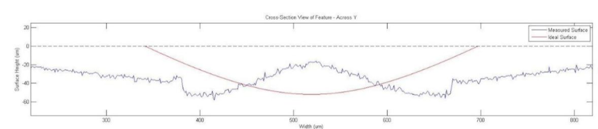
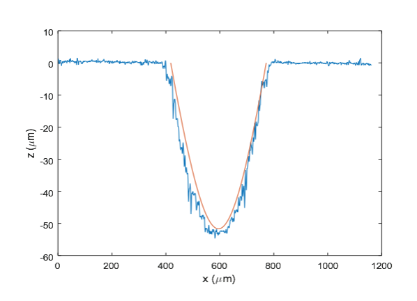
The magnitude of the offset error is approximately \(250 \mu m\). Given that the diameter specification is \(354.1 \mu m\) this is quite a significant offset. Another problem that is observable is a significantly wider actual dimater \(>800 \mu m\) than the actual specification. This is due to a shallow rake angle on the tool itself. The results of our toolholder improvement are shown below. The spindle speed we set was 3000 RPM at a depth of cut of \(1 \mu m\). The work material is titanium.
An overhead camera view of the cut is also shown below.

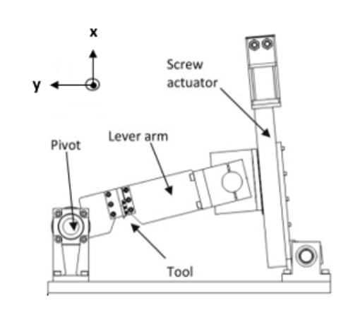
The keys to drastically improving the geometry of the final cut piece are come in the form of providing the additional translational adjustment. The essential elements of the CAD design of the toolholder are shown below.
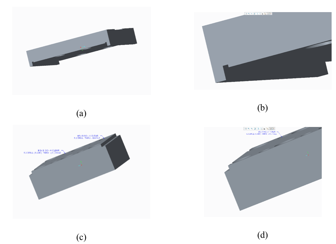
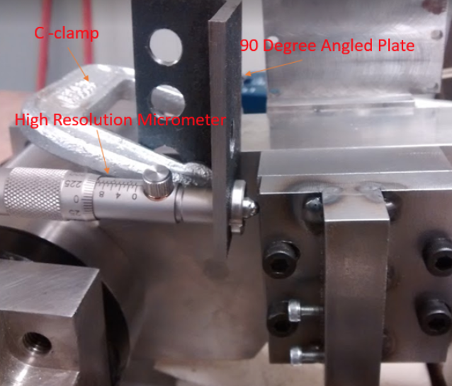
The front plate is bolted to the back plate with additional spacing around the bolts providing the range of adjustment along the sliding tract of the front plate to the back plate. This toolholder was made using a combination of spot welding, traditional milling and CNC milling. Along the sliding interlocking section, note the presence of an additional groove. This groove was cut to circumvent the possibility of imperfections along face of the bottom plate along that corner of the slide. Fine adjustment of the toolholder was made possible by a \(5 \mu m\) resolution micrometer shown below.
The full report for this project can be found here.