Pump Networks
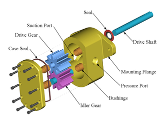
I worked at the reliability section of Narrows, VA branch of Celanese where wood pulp is turned into cellulose acetate and then extruded into cigarette filters. One persistent problem was of pump seals failing in a pump network. To illustrate the idea, I have below shown an exploded schematic of a gear pump. Cellulose acetate dope is a highly viscous compound. Much like cake batter. Fluid flows into the suction port, and is pushed outward into the pressure port at a higher pressure. The amount of pressure created is mainly a function of the clearance between the gear housing and the gears. With the pressure differential thus fixed by these clearances, the flow rate generated is linear with respect togear speed. These types of pumps are also called positive displacement pumps. In order to move the gears, a motor provides rotary motion to the drive shaft. A pump seal failure would result in dope overflowing past the seals.
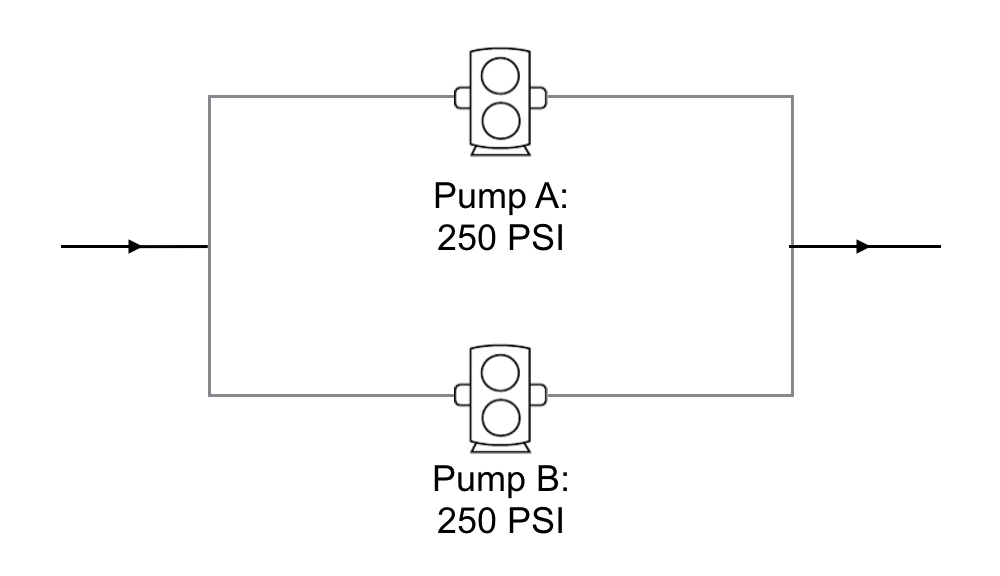
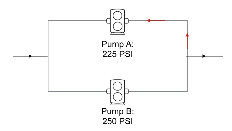
A number of possible reasons were initially proposed for why this might have occured, most explanations concentrated on the maintenance of the pumps and the quality of the seals. In fact, the problem lies in the nature of the placement of the pumps in the fluid network. In the figure below, two pumps are placed in parallel with eachother. You can of course have more pumps running in parallel, but two are sufficient to understand the downsides associated with this design. Pump A and B are running with the same pressure and all incoming fluids flow outwards with an increase of 250 PSI.
Suppose we operate the pumps at 450 RPM. If we look at the operating specifications of these pumps shown in the diagram below, we see that at 450 RPM, the pumps are generating a 10 GPM flow rate.
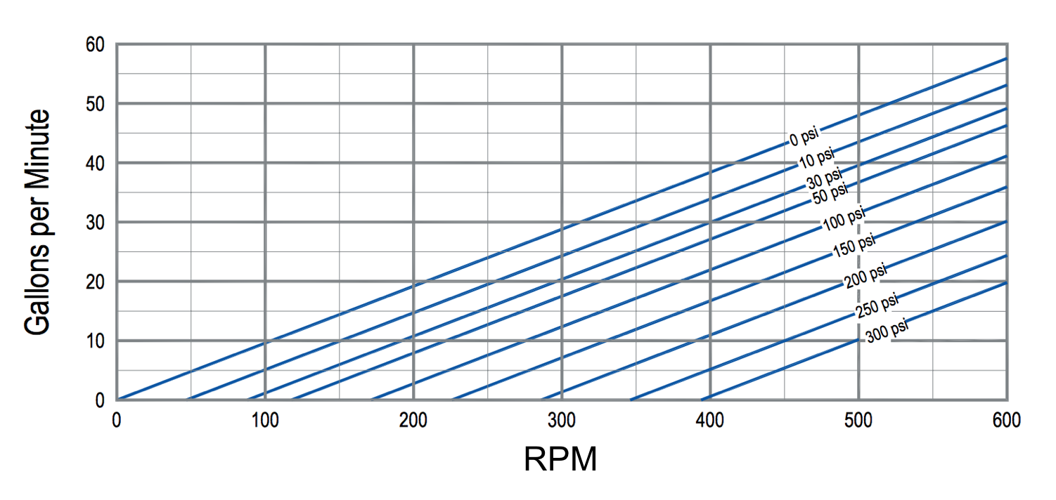
Note that the flow rate varies linearly with pump speed. Pressure is fixed. The total flow rate is the sum of the two, or 20 GPM. If one of the pumps needs to be serviced, or is taken out of order for any reason, only the flow rate is affected, but one pump can continue to provide 250 PSI of pressure at 10 GPM. Contrast this situation with two pumps put in series as shown below. Using the same pumps running at the same opearating conditions, we would generate 500 PSI at 10 GPM. That is, the pressures add together. All properties are exactly the same as with electric circuit networks, with pumps taking the same role as batteries.
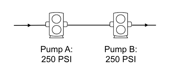
In this case, if one pump fails, the entire line is cut off. The parallel pump network has this redundant feature in its favor. The problem in the parallel configuration comes when pressure provided by the pumps decreases in an unbalanced way. Because pump A can not provide sufficient pressure, flow will reverse course and cause a seal failure. If these were batteries, flow would reverse, and the batteries would ignite if they are not rechargeable batteries. The advantage of the serial network, is that reduced pressure differentials would only lead to an overall reduction in voltage, and not catastrophy.
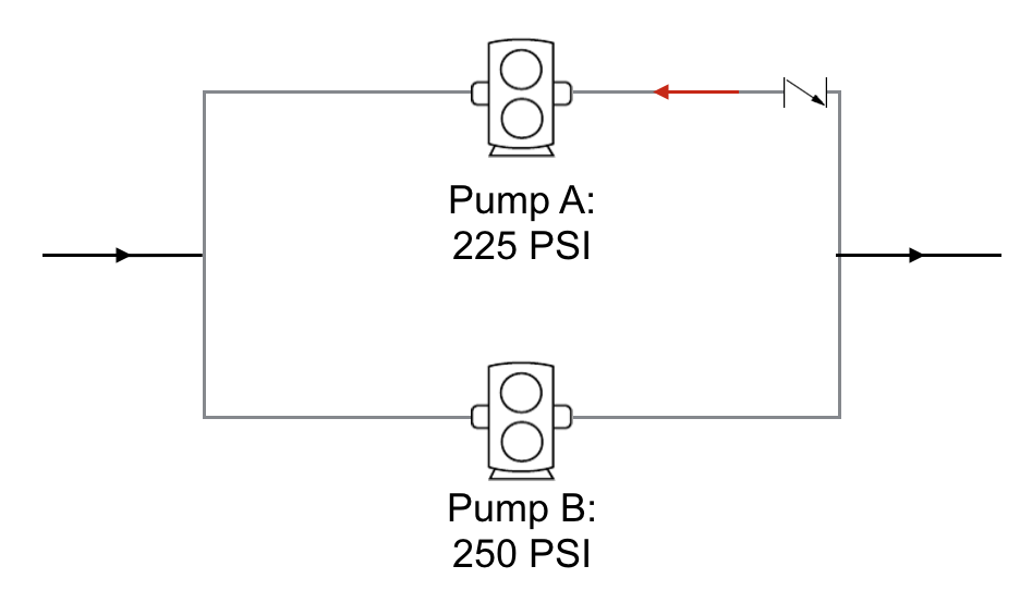
If we try to mitigate the problem by placing a check valve after pump A, a seal failure will still occur because pump A cannot provide the requisite pressure to overcome the check valve upstream pressure.
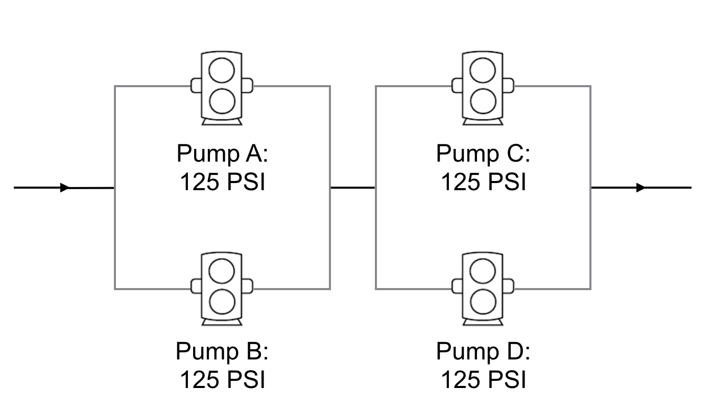
Thus, the only way to prevent failure is to prevent the pump from degrading in pressure capabilities. This is largely a function of how far away we are from the nominal operating pressure we choose to operate the pump at. In other words, if the lifetime of the pump is longest at 125 PSI and we are operating at 250 PSI, we should expect the pump to reduce in capability much sooner and more suddenly that if we operated at 125 PSI. If we want to retain the same 20 GPM flow rate and 250 PSI operating at the nominal pressure of the pumps, a more maintainable network would consist of four pumps connected as stacks of parallel pumps as follows.
The interesting aspects of this problem are that it generalizes to any realm where material is flowing in any serial or parallel configuration.